95110 Sannois - France


New Generation Valve Actuation
CAI EH® Compact Electro-Hydraulic Actuators
Presentation and Operating Principle
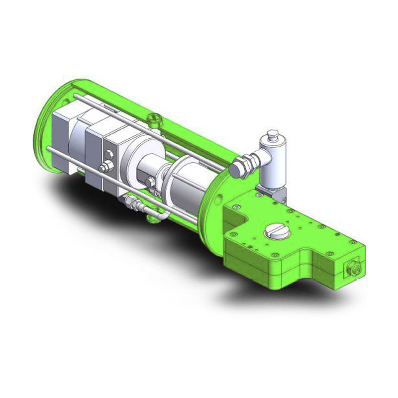
CAI EH Power Block
Several years of research have enabled us to achieve significant advancements in developing a range of power blocks perfectly suited for valve actuation needs.
The EH power block features, within a compact cylinder, an electric motor-hydraulic pump unit, a distribution and adjustment block, and a hydraulic thrust cylinder, all submerged in oil and sealed.
No mechanical components are visible externally on the cylinder.
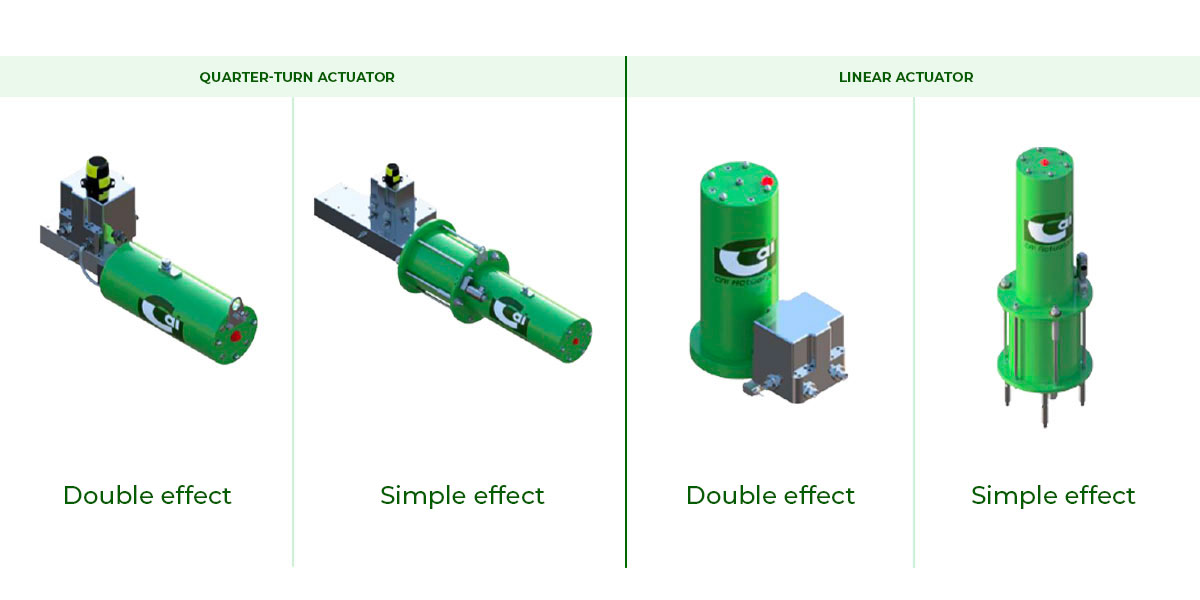
The EH power block is versatile, capable of operating in double-acting mode, single-acting mode with a spring return box, or with a hydraulic accumulator (using an additional connection block) for both quarter-turn and linear motion valves.
A particularly important patented regulation version will be discussed separately.
Exploded view of CAI EH power block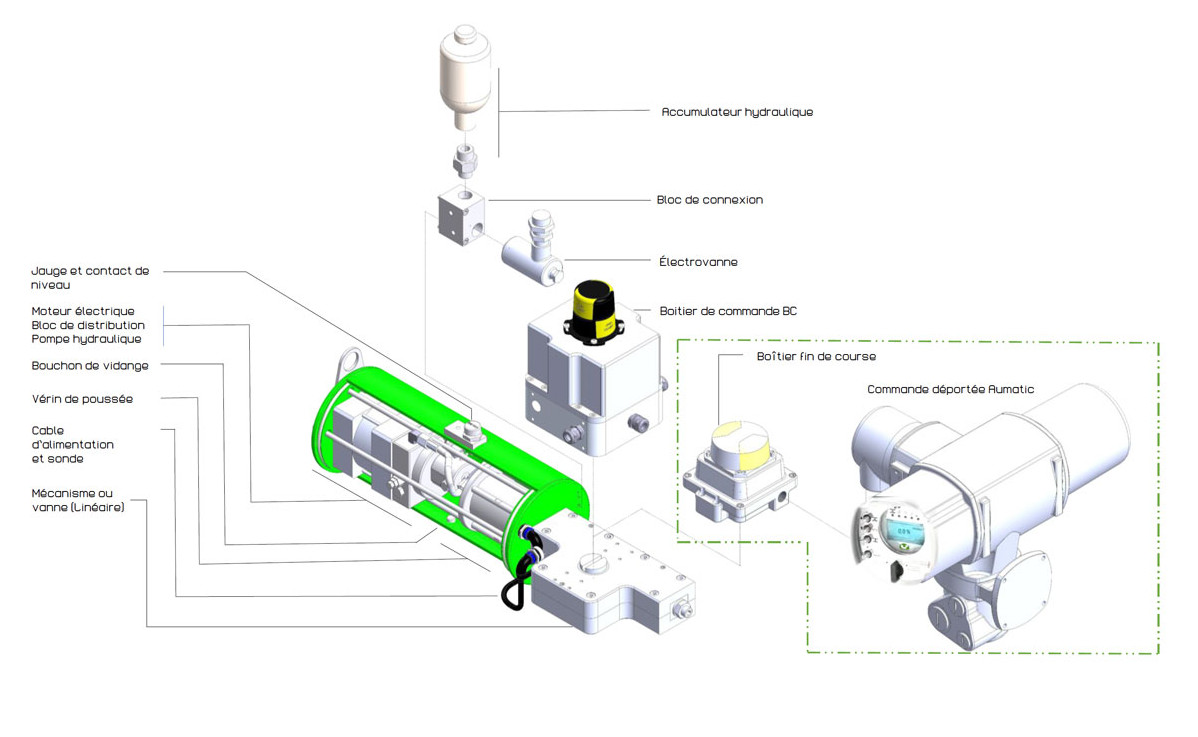
1. Composition
a. Electric motor :
Specifically designed for operation immersed in oil.
The motor is directly mounted on the rear flange of the housing.
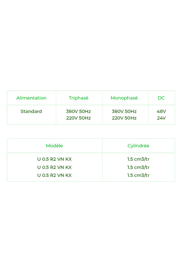
- Electrical power characteristics : (see table).
- Available powers: 0.6 / 1.5 / 3 / 10 kW. 2 poles 2800 rpm.
- Duty cycle*: Type S3 30% - 50% according to IEC 34 standard.
- The electric motor is equipped with a temperature sensor as standard, directly connected to the motor management electronic module. In case of exceeding the assigned temperature, the module stops the motor and signals an alarm
*Other duty cycles are possible by adjusting the amount of cooling oil.
b. Distribution block pump :
The hydraulic pump is coupled to the electric motor through the distribution block, which includes all necessary functions for a simple and precise application.
The flexibility of the hydraulic system allows for factory-adjusted pressures in opening and closing, effectively protecting the valve stem against abnormal forces.
 |
c. Hydraulic Cylinder The hydraulic cylinder provides the necessary power for the application. Its stroke, and thus its dimensions, depend on the application requirements. The cylinder is made from honed tubing, and the shaft, the only part in contact with the atmosphere, is made from ground and polished chrome bar to ensure good resistance against potential chemical attacks. Specific high-pressure seals ensure maximum longevity. |
 |
d. Drain Plug The drain plug (red) is always located at the bottom of the CAI EH power block. It is important to specify the horizontal or vertical position of the actuator when ordering. |
 |
e. Level Gauge The level gauge (yellow) is always located at the top of the CAI EH power block. It allows for easy visualization of the oil level. A minimum level contact (blue), which prevents the system from operating when the oil level is too low, is integrated into the CAI EH power block. |
 |
f. Connection Block In the case of a single-acting SE application, the connection block ensures the connection of the solenoid valve and, if applicable, the hydraulic accumulator. In specific versions, it is designed to integrate other components (manometer, pressure switch, manual control, etc.). |
|
g. Manual Control* The CAI EH power block comes with a standard manual control. To avoid manual pumping with a lever, we have provided a simple solution using a portable electric drill/screwdriver equipped with a hex bit, used directly on the shaft output. Power 1000/3000W - Speed 3000 RPM. *A lever-operated manual control can be integrated into the connection block. |
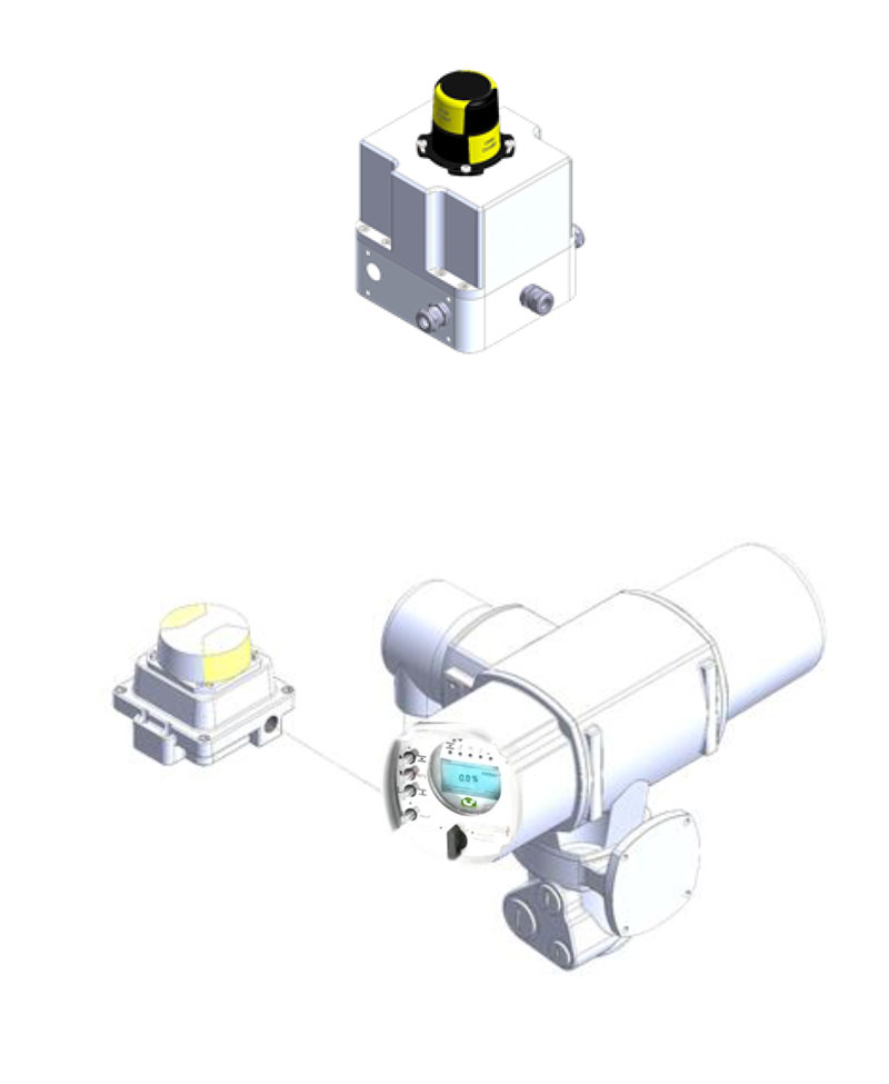
h. Control Box:
The management of the compact electrohydraulic EH block is ensured through three types of control boxes:
- Control Box BC:
This box consists of a power module for an ON/OFF function with a motor management module and a limit switch system. - Aumatic Control Box:
Positioning function, local and remote control with Bluetooth communication. This box consists of a limit switch module and a remote Aumatic system. - Aumatic S Control Box:
In addition to the features of the previous model, this version supports various fieldbus systems (Hart, Profibus, etc.).
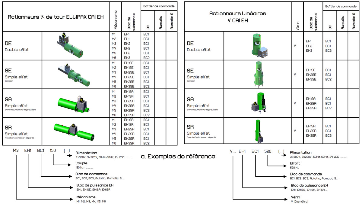
2. Available Versions
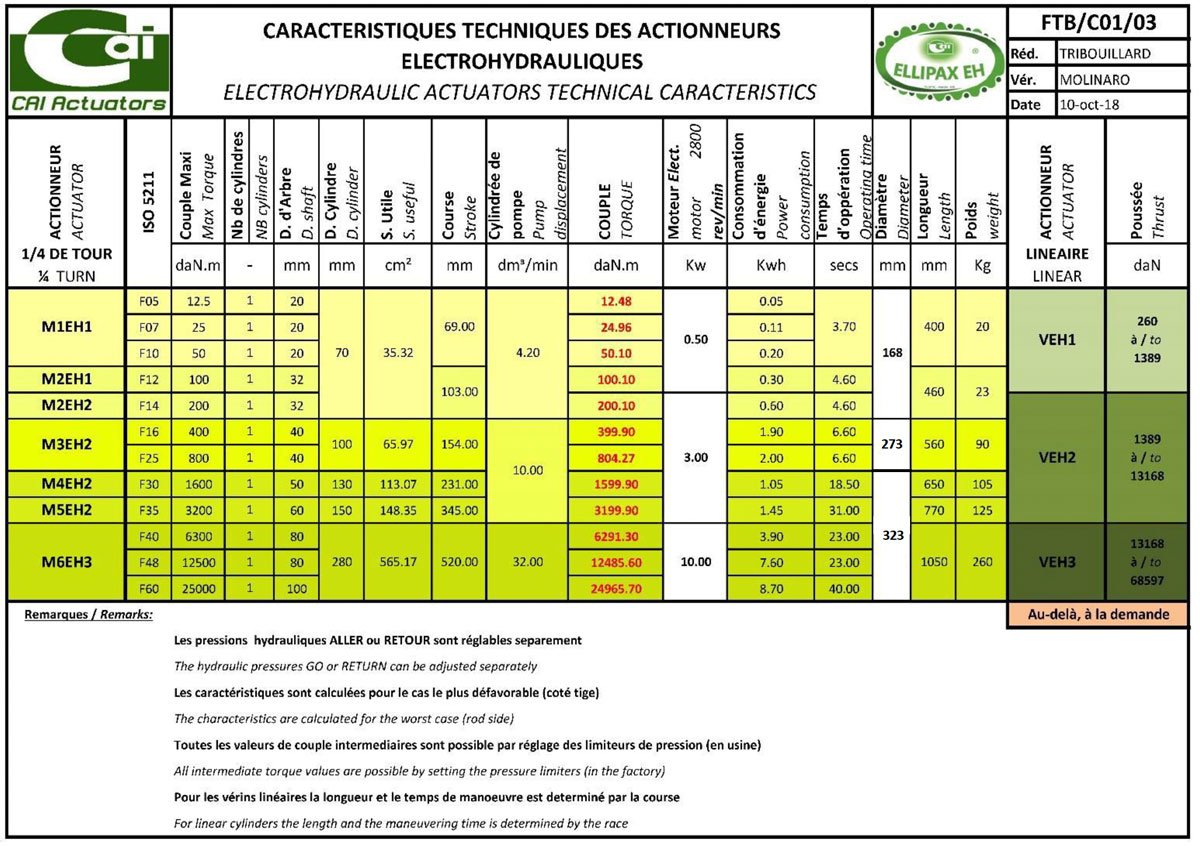
3. Technical Specifications
a. Performance and Technical Specifications - CAI EH Power Block :
4. Ellipax Quarter-Turn Actuator
a. Simple and Robust Construction:
The housing consists of two symmetrical, ultra-flat parts enclosing the entire mechanism. Due to its design, the number of parts is minimized.
b. Increased Lifespan:
The patented gear design allows for 3 to 5 teeth to be engaged at all times, significantly reducing the stress on the teeth.
c. Easy Disassembly and Maintenance:
A single hex key allows for the disassembly of the entire mechanism. The cylinders are held in a dedicated housing within the half-shells and do not require bolted connections.
d. Cylinder Design:
Using a patented latch system instead of tie rods, there are no protruding parts on the cylinders.
e. Centralized Lubrication:
A special study was conducted for lubrication. All moving parts are greased from a single point, including the bronze bearings.
f. Cost:
In the design and conception, cost considerations were a guiding principle. All parts are optimized for automated machining and simple, quick assembly.
g. Special Applications:
The most demanding applications, such as deep-sea, extreme cold, or aggressive environments, are achievable due to the system's design and the use of appropriate materials. (Special steels, INOX316, 17.4PH, ALLOY, etc.).
h. Standardization:
All our productions comply with ISO 9001, ATEX, PED, SIL1 and 2 standards and apply the 5211 standard for valve adaptation and the VDI/VDE standard for limit switch box adaptation.
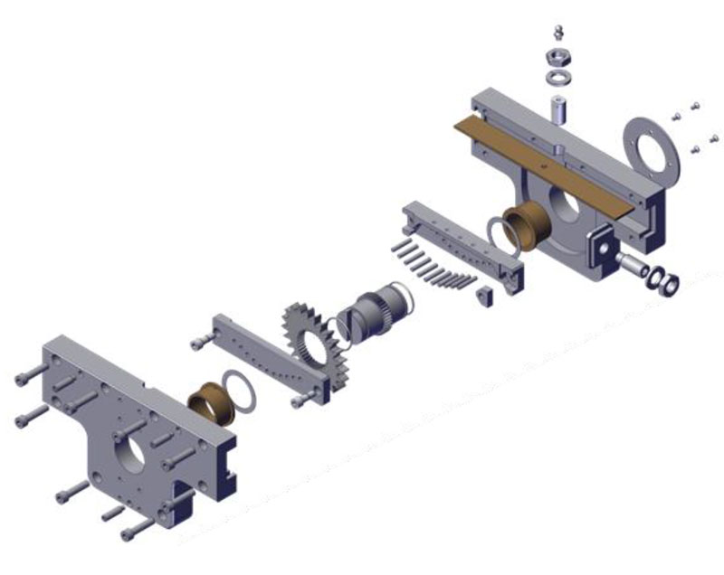
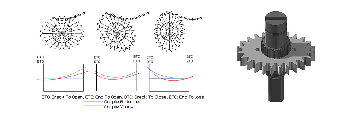
The next-generation actuator "ELLIPAX" is based on a mechanism utilizing an elliptical gear engaging with axes. This patented innovation allows the actuator's torque to be closely matched to the valve torque. Optimization and applied technology enable a reduction in size, weight, and consequently cost, while ensuring unmatched power and reliability. ELLIPAX allows for a maximum torque variation of R/r = 1.5. Moreover, by adjusting the position of the elliptical gear on the grooves of the sleeve, it can achieve intermediate positions based on the torque requirements of the valve.
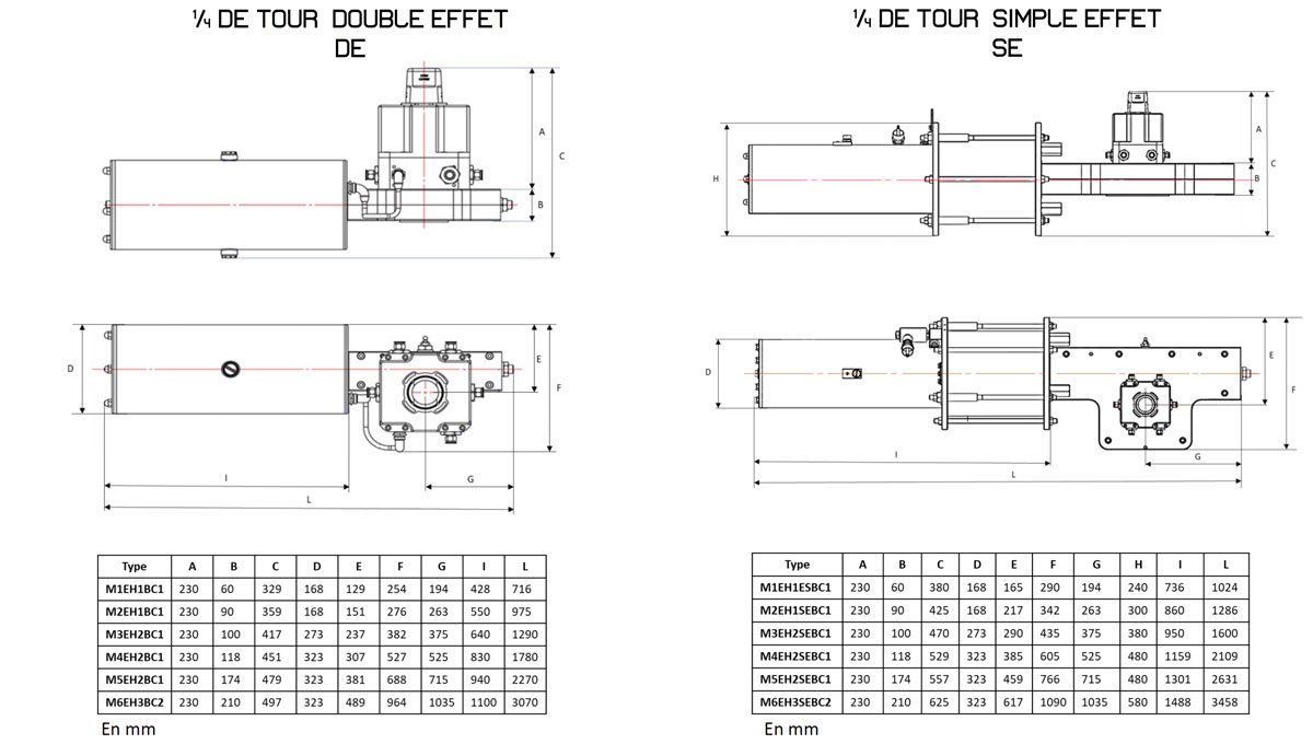
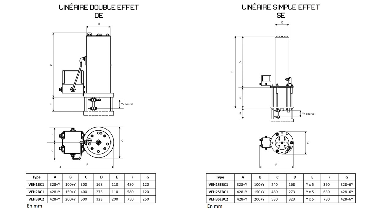
5. Dimensionnel
6. Applicable Standards
a. Certificates and Approvals:
- Quality Management according to ISO 9001/2015 | Bureau Veritas
- Pressure Equipment Directive compliance according to 2014/68/EU | Bureau Veritas
- Safety Integrity Level (SIL) certification | Bureau Veritas
- ATEX Directive 2014/34/EU certification | Bureau Veritas (LCIE)
a. Applicable Documents:
- EN 9001/2015: Quality Management System
- AEIA GS-R-3: QMS applicable for activities in the nuclear industry
- EN 60079-0 - 2018: Equipment intended for use in explosive atmospheres
- ATEX EN 60079-1 - 2015: Protection by enclosure "d" in ATEX zones
- EN 60079-6 - 2016: Protection by immersion "o" in ATEX zones
- ATEX EN 60079-34 - 2011: QMS for manufacturing equipment in ATEX zones
- ATEX EN 60079-36 - 2016: Non-electrical equipment for ATEX zones
- ATEX EN 60079-37 - 2016: Non-electrical equipment for ATEX zones (protection mode)
- ATEX Directive 2014/34/EU: Directive for equipment used in ATEX zones
- Directive 2014/68/EU: Pressure Equipment Directive
- Directive 2006/42/EC: Machinery Directive
- IEC 61508 SIL Directive: Functional Safety
7. ATEX Marking
The ATEX marking specifies the conditions for product use in zones with explosive atmospheres
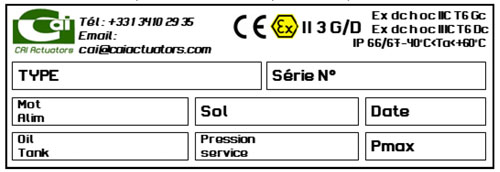
a. Product Classification:
- Device Group II
- Category 3
- Gas IIC Dust IIIC